
Introduction
Guitar pedals are really fun tools for when you want to change things up and try new styles of music. In this tutorial, I’ll walk you through how to build out a pedal kit or build a pedal from scratch! This guide will cover the components used in guitar pedals, websites where you can pick from some really awesome original and “clone” pedals, and ways to keep your build organized and easy.
Kits range from easy to advanced, but they are still very accessible for hobbyists. I had no prior experience with electronics, and I have had no trouble putting together these kits. If you are not familiar with the lingo used, don’t “fret” (ha). It will not prevent you from building a kicka** pedal that sounds great! Building pedals is an excellent way to start a new hobby in electronics, or even a business of your own!
-
-
Pick a pedal kit online that you’re interested in. It could be a distortion pedal, an overdrive, a reverb, a loop, whatever! If you want a specific pedal but it costs $200, chances are there's a clone you can build for $80 so get lookin!
-
If you like a particular band, you can check out what pedals they use by looking them up on Equipboard.com. Here I looked up Kurt Cobain from Nirvana. (He used 24 different pedals, maybe more!)
-
Here are a few reputable pedal kit companies:
-
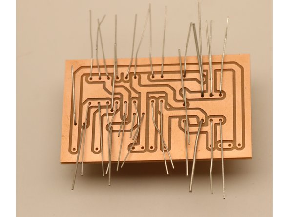
Mod Kits DIY: Pretty good, but tougher than some. Their kits run off of “point to point” wiring, which is a little different and a bit less clearly laid out than PCB’s.
-
Madbeans Pedals: These guys sell schematics for pedal designs, which is pretty cool if you’re going to etch your own PCB!
-
DIYGP PCBs & Kits: These are suuper easy to build. The PCB’s are marked out for each component. This guy also has an amazing guitar pedal channel on youtube DIY Guitar Pedals
-
Rullywow PCB's: This company makes super easy, super clear PCB’s. It’s plug and play. They even make PCB attachments that make wiring the 3PDT “stomp” switch way easier!
-
-
-
If your kit comes with all the components, get them together and separate them into groups: capacitors, resistors and diodes, transistors, and hardware.
-
If your kit does not come with components, you will have to shop for them using the list supplied in the kit. You can visit a place like Microcenter, or you can purchase components online from Small Bear Electronics or Mouser.
-
Each component type has its own marking convention. Sometimes you will get a guide to the colors and sizes you are given, sometimes you will not. I have attached the guides that helped me most decode all the numbers and letters and colors.
-
-
-
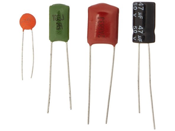
Film Capacitors: Wide-flatties. There are usually values written on the sides of the capacitor. Give those numbers a google and it’ll tell you what value they are.
-
Ceramic Capacitors: Small and circular. They have very small writing on the sides.
-
Radial Electrolytic capacitors: Long-tube-ies. They’ll usually be polar (meaning one side is positive and one is negative) so make sure you’re connecting them in the right direction according to your diagram!
-
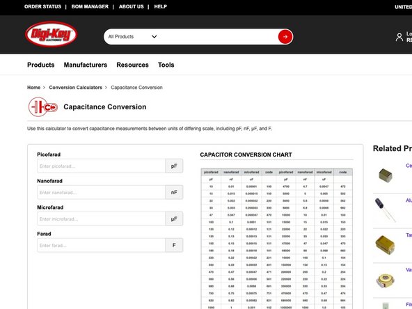
Capacitance Conversion Calculator This guide will help if your parts list gives you capacitor values in different values than the markings on the components, ie: 1 nanofarad (nf) = .001 microfarad (㎌)
-
-
-
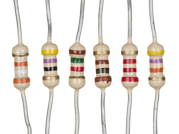
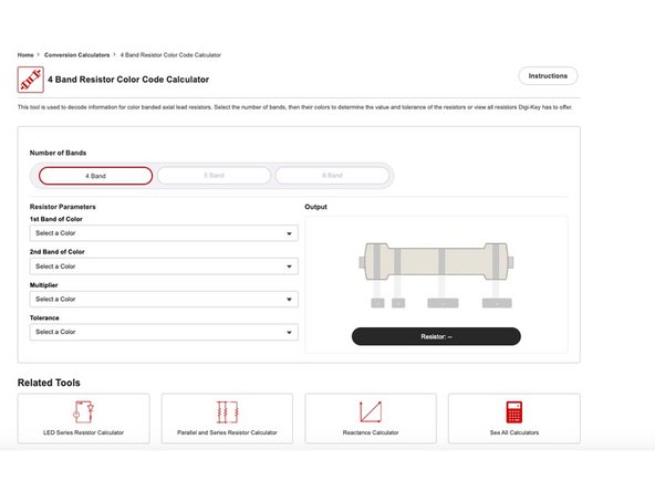
Luckily, resistors are usually nonpolar, so no need to worry about which way they connect. They use a 4-6 color coded band convention. To figure which is which, use this guide: https://www.digikey.com/en/resources/con...
-
Heads up: it's very easy to mix up resistors! For instance, a 220 Ohm and a 220K Ohm are one band color apart, but far from interchangeable. Double check each resistor before you solder.
-
-
-
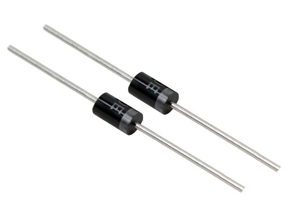
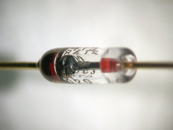
Diodes are small and look like black and silver or glass resistors. They are often polar! so it matters which way you connect them in. Make sure you look for a stripe closer to the end on one side and that’s your cathode (-) side.
-
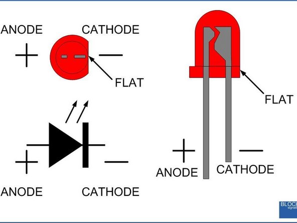
LED’s or light emitting diodes make the light that let you know when the effect is off or engaged. They will almost always require a resistor to prevent burning them out, so make sure that gets attached. They are polar, and the long leg is the positive end (anode).
-
-
-
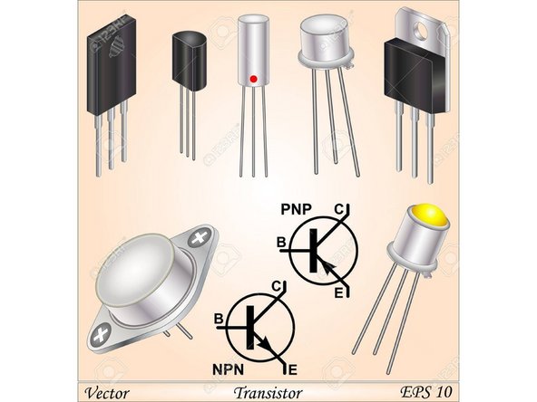
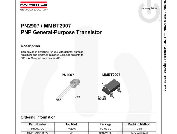
These have 3 leads, an Emitter, Base, and Collector (shown in diagrams as EBC). It’s important to find out which leads are which and wire them according to the diagrams. Sometimes they are flat on one side, which will help to orient as shown in the diagram.
-
If you're having a hard time figuring out which leads are which, you can find it in the transistors datasheet by Googling the name of the transistor ie: PN2907
-
-
-
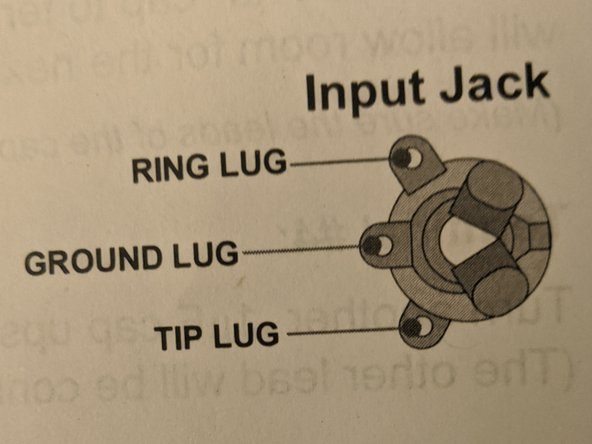
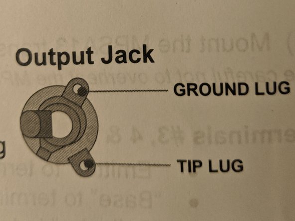
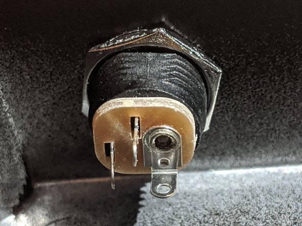
The input jack has 3 lugs and the output jack has 2 lugs. Convention says to mount the input on the right and output on the left, but it doesn’t really matter. Go off of what the kit says.
-
-
-
DC Power Outlet: If your pedal plugs into the wall, it will come with a 3 pin power supply. The pins, are positive, negative, ground.
-
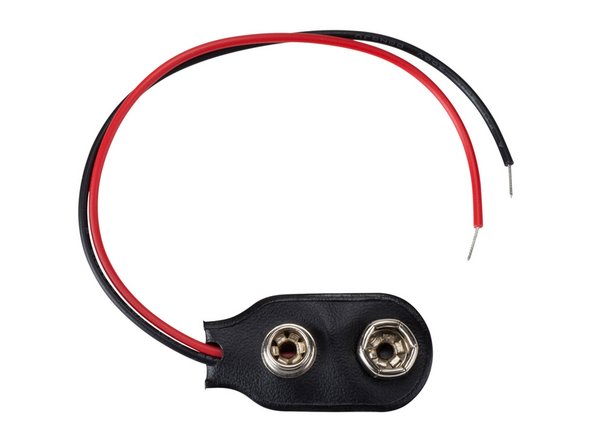
Battery Snaps: These allow you to hook up a 9 volt battery to your pedal. Red line is a positive terminal and the black connects to ground.
-
Many pedals come with both a 9 volt and DC power supply. They will be wired together and can be used interchangeably.
-
-
-
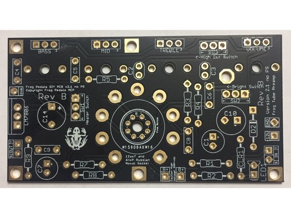
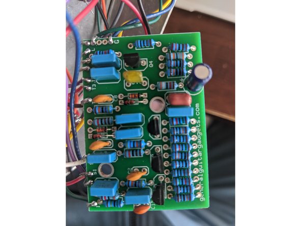
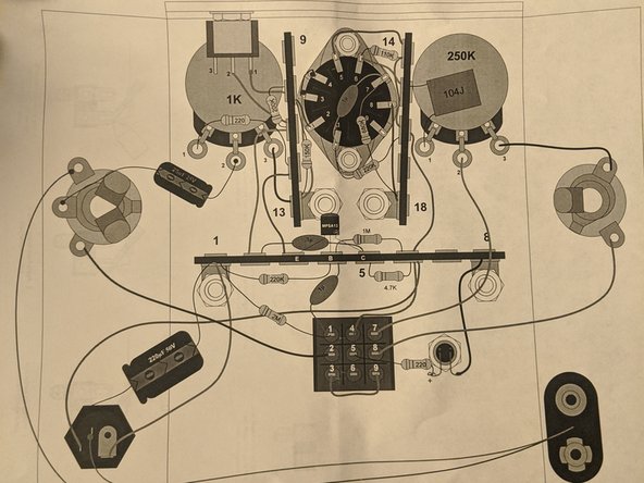
This is your board. Each hole represents a lead where a component will connect, and the white outlines/markings correspond to each component in the kit.
-
Each has a ring of metal around the hole called the pad. These heat up when you're soldering and accept the solder, fusing the component to the PCB.
-
-
-
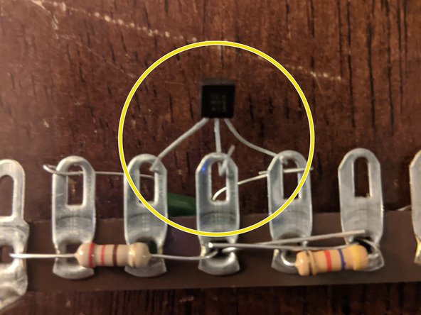
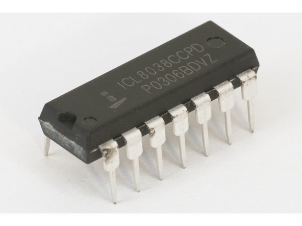
Integrated circuits These are tiny microcontrollers, and they kinda look like little black bugs with silver legs.
-
If your kit has one of these, you'll have to get the orientation exactly right, but soldering them in is the same as all the other components.
-
-
-
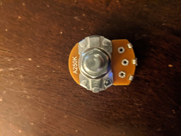
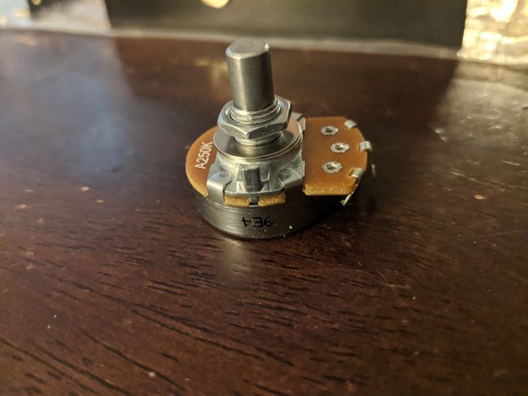
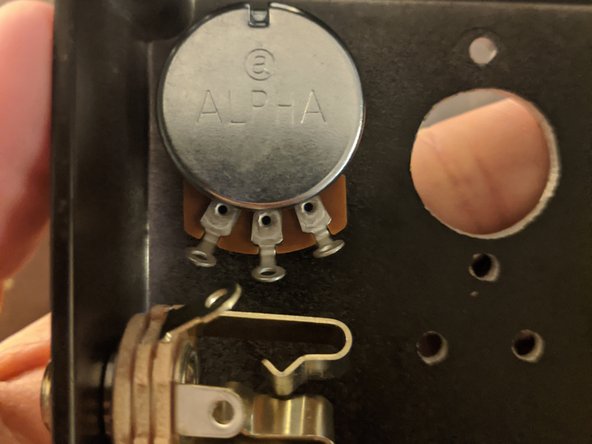
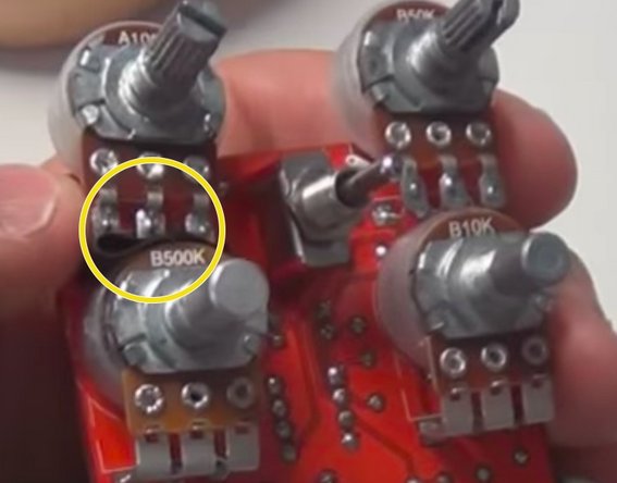
These are your knobs that control volume, gain, etc. They come all ranges of current, and in two main types: Audio (with markings beginning with A) and Linear (with markings beginning with B).
-
They have three lugs which will be polar, so wire them according to the diagram.
-
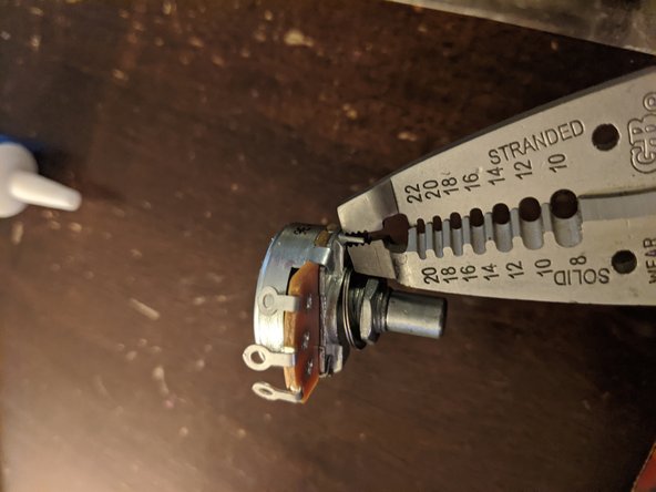
Some pots have an annoying little tab on the top of the case that will prevent it from laying flush in your pedal. Snap them off with a pair of pliers
-
-
-
Solder components in order of shortest to tallest, which is generally:
-
1) Resistors and Diodes 2) Film and Ceramic Capacitors 3) Transistors 4) Radial Capacitors 5) Wiring
-
Soldering “tips”
-
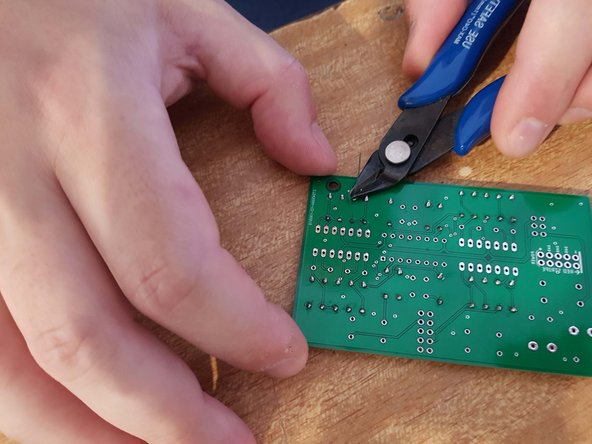
Feed the leads through the holes on your PCB and press your component tightly against the board. On the back of the board, bend the leads to the sides so it stays put.
-
Touch the soldering iron to the junction where the leads touch the metal pad on the board to preheat it (2 seconds). Try not to touch the plastic on the board.
-
Now touch your solder to the tip of the iron until it melts (less than 1 second), then drag the solder over the leads. Remove the iron and let cool.
-
Repeat as many times as necessary until you have a strong joint
-
Bend the remaining portion of the lead away from the board and clip the excess.
-
-
-
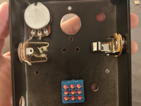
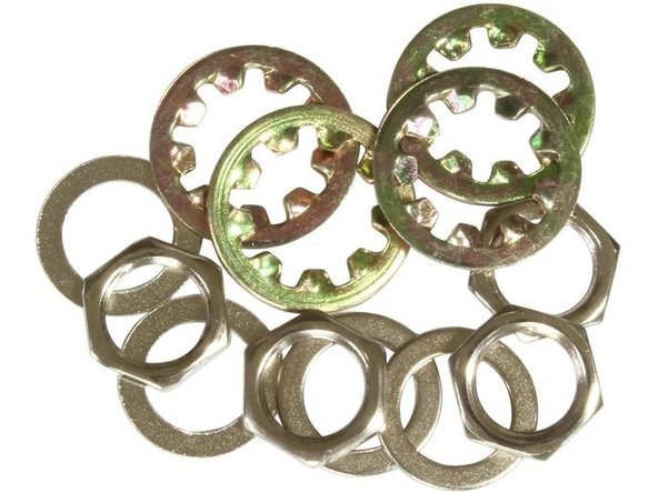
Most of the off board hardware (input/output jacks, switches, 3SPDT, potentiometers will go on with hex nuts. Remove the nut, place the component through the hole, and spin the nut back on from the outside of the enclosure.
-
There may be a washer or rubber ring on the component, which should be installed on the inside of the enclosure touching the wall.
-
-
-
Using your kit's wiring diagram, begin wiring together your off board components (switches, pots, power supply, and jacks).
-
Cut lengths of wire long enough to reach between terminals, but not so long that they crowd your box and push components and leads into each other.
-
Strip a ¼ inch section on each side of the wire.
-
Feed the stripped wire through the first lug and fold it to give you the most contact with the pad/terminal. Check to make sure the wire still reaches your other terminal.
-
Touch the iron to the pad/terminal and the wire (at the same time if possible), touch solder to it, and drag the tip across the connection. Repeat until you have a solid joint.
-
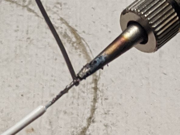
“Tinning” wires: Adding solder to your wires before soldering them. To do this, heat up the stripped portion of your wire (2 seconds) and then add a small amount of solder to them. This is optional, but will make for better connections.
-
-
-
Once you finish all your soldering, it’s important to test the effect before closing it up. You will be able to diagnose and fix any circuit shorts before it all gets tucked into the enclosure.
-
Carefully plug in your pedal (or install the battery if it runs off a 9 volt).
-
Lower the volume on your amp until you can barely hear the guitar to prevent blowing your speaker.
-
Using a pencil or piece of rubber, move the wires by pushing the insulated portion a few mm to each side. If you hear a pop or crackle, make a note of the wire and reinforce the solder joint when the pedal is off.
-
Make sure that your jacks do not make contact with any exposed metal or components when plugged in!
-
-
-
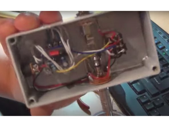
If you hear no noise after you screw on the lid, you may have a short inside the box. Try turning knobs and clicking the switches, listening for any change in the signal.
-
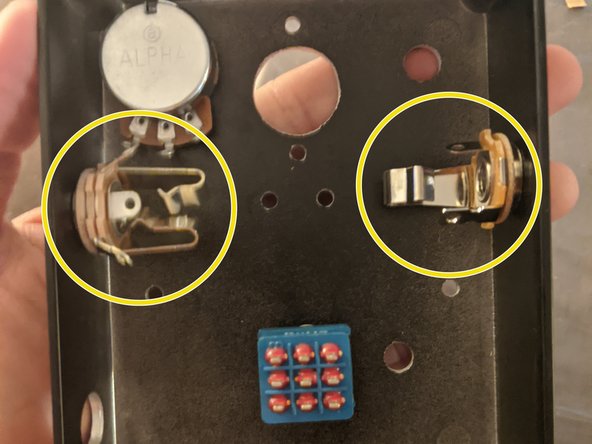
It's common to have a component improperly contacting the enclosure or another component. Potentiometers, output and input jacks, and switches are common sources of shorts because they have large portions of exposed metal. If you find a point where components might be touching (see yellow circle), separate them with electric tape.
-
Make sure all your polar components are installed in the right directions. The stomp switch is also easy to mix up.
-
Make sure that you have not misjudged the value of a component, for example a 220 Ohm switched for a 220K Ohm resistors.
-
Wiggle wires and make sure it’s not a bad connection. Make sure no wires are touching other components with their non-insulated portion, and reinforce weak solder joints.
-
Make sure your electronic components are tightly packed with no stray or extra long leads which could be causing a short.
-
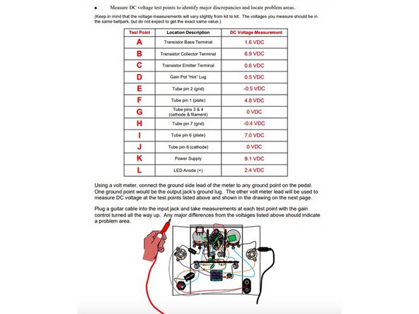
Finally, if none of these are the problem, check all of your components and wiring with a multimeter. Many kit producers have voltage guides for each pedal with expected values so you can check you're getting the right voltage at different points.
-
-
-
Congrats! You have just built a fully functioning guitar pedal! On the cheap, no less!
-
Seriously, there is no better feeling than plugging in an effects pedal that you built yourself (except maybe giving one as a gift)! It will have a sound like nothing else on the market because you built it.
-
Pedals are exciting projects for both people who love playing guitar and want to learn about simple circuits. If you have made any pedals after reading this guide, please post a response!
-


Cancel: I did not complete this guide.
One other person completed this guide.